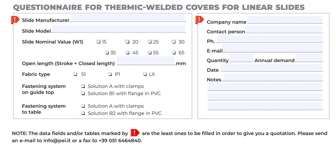
Thermo-welded bellows for linear rails
Thermo-welded bellows protections for Linear Rails
The cutting precision of the PVC supports allows a precise slide holding and the range of materials used are characteristics that make PEI bellows widely used in all industrial sectors.
Data
Materials
Flanges
Documentation
Data
Thermic-welded bellows for linear slides
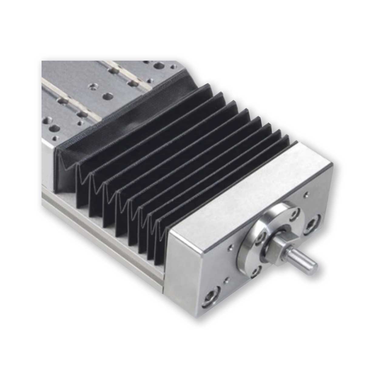
Example of bellows mounted on linear slides
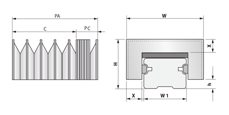
PA = Open Length
C = Stroke
PC = Closed Length
| Standard bellows dimensions for linear slides | |||
| Rail nominal value W1 | Fold height X | Total height H | Rail offset h |
| 15 | 19 | 36 | 5 |
| 20 | 19 | 40,5 | 5 |
| 25 | 19 | 43 | 7,5 |
| 30 | 19 | 51 | 8 |
| 35 | 19 | 51 | 9 |
| 45 | 19 | 61 | 10 |
| 55 | 25 | 73 | 15 |
| 65 | 32 | 90 | 15 |
Bellows materials for linear rails
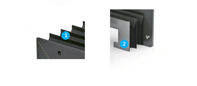
| Standard materials for linear slides Bellows | |||
| Type of material | Support | Bellows | Closed length for 1000 mm of Open length |
| S1 | PVC 0,5 | PVC + Polyester + PVC 0,25 (TEMAT020) | 90 |
| P1 | PVC 0,5 | Polyurethane + Polyester + Polyurethane 0,25 (TEMAT015) | 90 |
| LX | PVC 1 | Polyurethane Panox / Kevlar + Polyurethane 0,33 (TEMAT169) | 150 |
Flanges
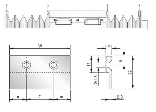
Flanges Bellows Heat sealed for linear slides
Solution A: Fixing clamps
Solution suitable for harsh work environments and in the presence of refrigerants.
The “M” area must be shielded with sheet metal fixed on the table bench.
Usable for fixing the bellows in all positions 1 – 2 – 3 – 4,
with plate or corner supports prepared by the customer.
| Dimensions solution A | |||
| Rails | W | C | No. HOLES |
| 15 | 52 | 26 | 2 |
| 20 | 57 | 29 | 2 |
| 25 | 63 | 32 | 2 |
| 30 | 68 | 34 | 2 |
| 35 | 72 | 36 | 2 |
| 45 | 83 | 28 | 3 |
| 55 | 104 | 35 | 3 |
| 65 | 128 | 32 | 4 |
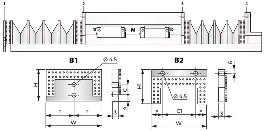
Solution B: Flange fixing with Velcro (B1 and B2)
Solution suitable for dry working environment
The “M” area must be shielded with sheet metal fixed on the table bench
* Standard PVC flanges = B1 and B2
* Flange mounting
Pos. 1
a) Fasten the standard type 1 flange to the rail.
b) Join the bellows to the standard type 1 flange by pressing strongly.
Pos. 2-3
a) Fasten the standard type 2 flange to the table or plate with screws.
b) Join the bellows to the standard type 2 flange by pressing strongly.
Pos. 4
a) Fasten the standard type 2 flange with screws to the angle prepared by the customer.
b) Join the bellows to the standard type 2 flange by pressing strongly.
N.B. The fixings shown in Pos. 1-4 are interchangeable.
| Dimensions solution B | ||||||
| RAILS | W | H | C | H1 | C1 | NO. HOLES |
| 15 | 56 | 36 | 0 | 42 | 26 | 2 |
| 20 | 61 | 40,5 | 8 | 46,5 | 29 | 2 |
| 25 | 67 | 43 | 8 | 46,5 | 32 | 2 |
| 30 | 72 | 51 | 8 | 54 | 34 | 2 |
| 35 | 76,5 | 51 | 18 | 53 | 36 | 2 |
| 45 | 87,5 | 61 | 18 | 62 | 28 | 3 |
| 55 | 108 | 73 | 18 | 69 | 35 | 3 |
| 65 | 132 | 90 | 18 | 86 | 32 | 4 |
Bellows Questionnaire for Linear Rails
